Hi, and thanks for response...
so
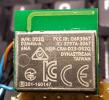
in attach there is a picture of the D52QD2M4IA module.
The wiring I used is:
H202 -> TO ARDUINO PIN FOR RESET FUNCTION
H203 -> VCC
H204 -> GND
H206 -> TO ARDUINO PIN FOR SUSPEND FUNCTION
H207 -> TO ARDUINO PIN FOR SLEEP FUNCTION
H209 -> PORTSEL TO GND (ASYNC)
H210 -> BR2 TO VCC
H211 -> UART TX TO ARDUINO RX
H212 -> UART RX TO ARDUINO TX
H213 -> BR1 TO VCC
H214 -> BR3 TO VCC
H217 -> RTS TO ARDUINO INPUT PIN
BR1-2-3 to VCC = selection of 57600bps serial UART speed
When Arduino starts it execute this routines...
// module reset
void hardwareReset() {
[... some other code ...]
digitalWrite(RESET_PIN, LOW);
delay(5);
[... some other code ...]
hw_reset_count++;
delay(5);
digitalWrite(RESET_PIN, HIGH);
[... some other code ...]
}
// **************************************************************************************************
// * ANT Management Routines
// **************************************************************************************************
void antBegin() {
pinMode(SUSPEND_PIN, OUTPUT);
pinMode(SLEEP_PIN, OUTPUT);
pinMode(RESET_PIN, OUTPUT);
pinMode(RTS_PIN, INPUT);
[... some other code ...]
digitalWrite(RESET_PIN, HIGH);
digitalWrite(SUSPEND_PIN, HIGH);
digitalWrite(SLEEP_PIN, LOW);
//This should not be strictly necessary - the device should always come up by itself....
//But let's make sure we didn't miss the first RTS in a power-up race
hardwareReset();
}
Image Attachments

Click thumbnail to see full-size image

