Each device profile is identified by its own icon(s), which can be used on the packaging of certified devices to help consumers understand which products will work together. You can find the device profile PDFs under the documents tab of the Download page.
The ANT+ Tracker Device Profile defines interoperable wireless communication between an asset tracker and a display device. An asset tracker is a device that is able to gather information about the location, distance, bearing, and status of multiple assets, and transmit that information over ANT to a receiving display device. An asset tracker also transmits identifying information about each asset such as its name and color, as well as status information about each asset such as whether the GPS signal has been lost for the device, if its battery is low, or if it should be removed from the display.
The ANT+ Asset Tracker Device Profile allows the status of up to 20 assets to be updated at a minimum rate of once every 2.5 seconds. It also allows for multiple display devices to receive asset information from an asset tracker over the same channel.
![]()


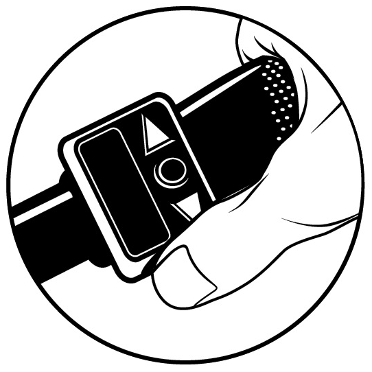
The ANT+ Dropper Seatpost Device Profile defines the wireless control and status messaging between ANT+ controller devices and bicycle dropper seatposts. It enables a user to wirelessly lock and unlock the valve on their dropper seatpost so the seat height may be manually adjusted without the need for a hydraulic or pneumatic controller on the handlebars.
An ANT+ dropper seatpost (seatpost) is able to communicate wirelessly over the ANT wireless protocol, and uses a single bidirectional channel to both report its current configuration/status and receive commands from ANT+ controller devices. The ANT+ controller device may be a bike computer, handlebar mounted remote, or mobile phone application capable of displaying the dropper seatpost’s status and/or sending unlock/lock commands to the seatpost.
In addition to its current valve lock status, the seatpost also reports its battery status, product information and additional supplementary data to the ANT+ controller device.
![]()

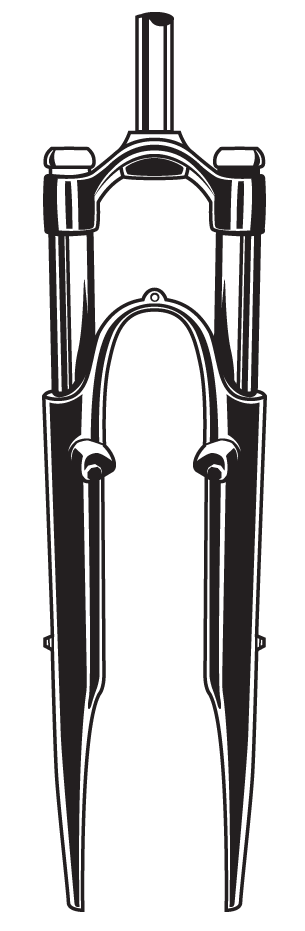
The ANT+ Suspension Device Profile is designed to receive data from and send settings adjustments to bicycle fork and/or rear shock suspension units. This allows riders to monitor and/or control their suspension system in real-time as they ride.
More advanced suspension units provide a lock function, adjustable damping, and/or an automatic suspension adjustment mode. Riders using suspension units with these features may choose to lock their suspension, or choose a higher damping setting when riding uphill; and unlock it, or choose a lower damping setting when on downhill sections. Alternatively the rider may choose to enable the auto-unlock mode, such that the suspension self-detects the changes in terrain or riding style and automatically unlocks the suspension when required.
An ANT+ suspension sensor is a bike suspension unit that is able to communicate wirelessly over ANT+. It may either be a bicycle fork suspension unit, a bicycle rear shock suspension unit, or a combined fork and rear shock system. In the case of the fork and rear shock system, the two sub-units either communicate wirelessly on a separate network, or may be wired together. Regardless of its type, an ANT+ suspension sensor uses a single ANT+ channel to broadcast its status to the display. The display may be used to send new settings back to the suspension sensor to lock or unlock the suspension unit, adjust the damping factor, and change the operating mode. These messages are sent as required in the reverse direction.
![]()
The ANT+ Extended Display Device Profile defines interoperable wireless communication between two displays where by one display behaves as an extension to the other display. This profile allows the main display or central data receiving node in a network, referred to here as a Data Aggregator (DA), to be extended by a single auxiliary display, referred to here as an Extended Display Device (EXD).
Typically, the EXD is a more portable device than the DA, with a simpler, relatively limited user interface, and lower battery capacity. These limitations make it difficult for the EXD to connect directly to multiple sensors, and provide an interface for users to configure the EXD. The Extended Display Profile defines a topology and messaging scheme that allows the EXD to be configured by a DA, and for the EXD to receive, through the DA, specific aggregated data and alerts derived from any number of feeder devices.
![]()
A DA may be connected to and receiving data from any number of end devices. These devices may be ANT+ sensors such as a heart rate monitor or bike speed and cadence sensor, other wireless technologies such as GPS, or sensors in-built into the data aggregator such as ambient temperature.
An ANT+ racquet sensor is a portable sensor attached to a racquet that allows an athlete to measure and record a variety of real-time racquet sport parameters. Sport specific data such as ball speed, number of shots, shot selection and swing accuracy can be detected by the racquet sensor, stored, and transmitted in real time to a display device. The display device may be a watch, cell phone or other type of personal display.
The display device may also contain user entered data (e.g. set count, match count, current score) and additional data transmitted from other ANT+ sensor devices (heart rate, average running speed, etc.). A mechanism is provided to transmit this data to the racquet sensor for storage as the sensor may act as the primary storage device.
Session information stored in the racquet sensor may also be transmitted as a FIT file to the display device or a personal computer (PC). In the alternate configuration where the display device is the primary storage device, the display device may transmit its FIT file to a personal computer upon request.
![]()

An ANT+ sync client or sync host may be used to record and store activity or sports information. This allows the user to review their activities at a more convenient time, potentially with a personal trainer or health professional.
An ANT+ sync client is typically a personal device such as a sports watch or a smart phone. Data such as speed, distance, or heart rate is collected and stored from multiple sensors including other ANT+ sensors. Once the user has completed their activity, this data is then made available for download by an ANT+ sync host such as a PC, phone or tablet.
Stored data is formatted according to the Flexible and Interoperable Data Transfer (FIT) protocol and transferred using ANT-FS to ensure interoperability.
![]()
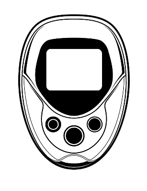
Muscle oxygen (SmO2) is a measure of the percentage of hemoglobin that is saturated with oxygen in the capillaries of a muscle. This value typically decreases as a muscle does work, for example when a person is exercising, and increases when blood circulation brings new oxygen to the muscle. The percentage of muscle oxygen varies from muscle to muscle depending on which muscle is used to perform a particular action.
A muscle oxygen monitor may be used by athletes to monitor the intensity of their training, and by coaches and physiotherapists to identify which muscles are being used when. An ANT+ muscle oxygen monitor provides a real time indication of the percentage of muscle oxygen in a particular muscle, which is transmitted wirelessly to a display such as a sports watch, mobile phone or tablet, and/or a PC.
An ANT+ muscle oxygen monitor may also store measurement data for transfer to a collection device. The data in the file is formatted according to the Flexible and Interoperable Data Transfer (FIT) protocol and transferred using ANT- FS.
Once an ANT-FS session is established, any stored data available can be downloaded from the muscle oxygen monitor. The display/collection device may then maintain the ANT-FS session allowing for periodic file transfers of data, or it may disconnect the ANT-FS session, at which point the sensor shall return to the real time data broadcast.
![]()

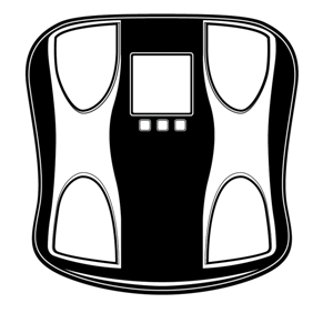
ANT+ weight scales are devices primarily used to measure the weight of the user that is placed on them. This requires the user to stand on the scale to take a measurement of the user’s weight.
The weight scale measures a user’s weight and, if the scale has access to more specific user information such as height and gender, then the scale may be able to calculate user specific information as well. The weight scale may broadcast this information to an ANT+ compatible receiver, or store it for transfer at a later date. The scale may have an integrated display, allowing users to enter profile information. The scale may also receive user profile information from a watch or other device.
One key aspect for the weight scale message definition is the incorporation of user specific data for calculating parameters that cannot be directly measured. Such data contains parameters that describe the user’s height, age, gender, and other relevant details that may be required for more complex measurements and calculations. The User Profile contains this information and can be provided to the scale by the display device or, depending on the scale’s capabilities, can be input directly through the scale’s user interface.


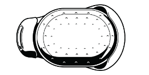
A stride based speed and distance monitor (SDM) is a personal body-worn device that allows the wearer to measure the number of strides taken, the speed at which he or she is traveling and/or the distance he or she has covered based on stride measurements and calculations. Some examples of SDMs include the foot-worn pods that go on, or in, a shoe and reconstruct strides to compute speed and distance while walking or running. Similarly, pedometers that may be worn on the waist or elsewhere are also considered SDMs. There are other profiles that allow for the measurement of speed and distance obtained from sensors that are not stride based. If there is some uncertainty about what device profile to use, please contact the ANT+ Alliance at [email protected] for more information.
SDMs are worn on, or close to, the body and transmit stride, speed and/or distance information to a watch or other display device. Some SDMs can compute additional information such as cadence. The display device can be a watch, cell phone, piece of fitness equipment, or other personal display device.

![]()

![]()

Light electric vehicles (LEVs) provide point-to-point transportation for one person and some cargo at speeds and costs that are moderate. LEVs range in size from electric bicycles to one-person cars.
The ANT+ light electric vehicle provides a variety of information such as current speed, distance travelled, remaining battery life and range, and current state information (such as lights on/off, gear state and travel mode). An ANT+ LEV display is used to communicate this information to the user, and may also provide an interface through which a user may control the LEV’s state. The display device may be a bike mounted unit, watch, cell phone or other personal display device. The purpose of the ANT+ LEV device profile is to provide a robust means of interoperable communication between LEVs and displays.
Many LEVs have a gear system that may be manually or automatically controlled. Some may have defined “travel modes” that allow the LEV to operate within economical, normal and higher power ranges. Some LEV’s may also provide peripheral devices such as headlights and/or indicator signals. These system features may be controlled on the LEV itself, or through a sophisticated display’s user interface.
Simple displays may not provide a user interface and are only used to interpret the data sent from the LEV. More sophisticated displays may provide an interface for the user to request a change to the LEV system, such as changing gears or travel mode, and controlling lights or turn signals.


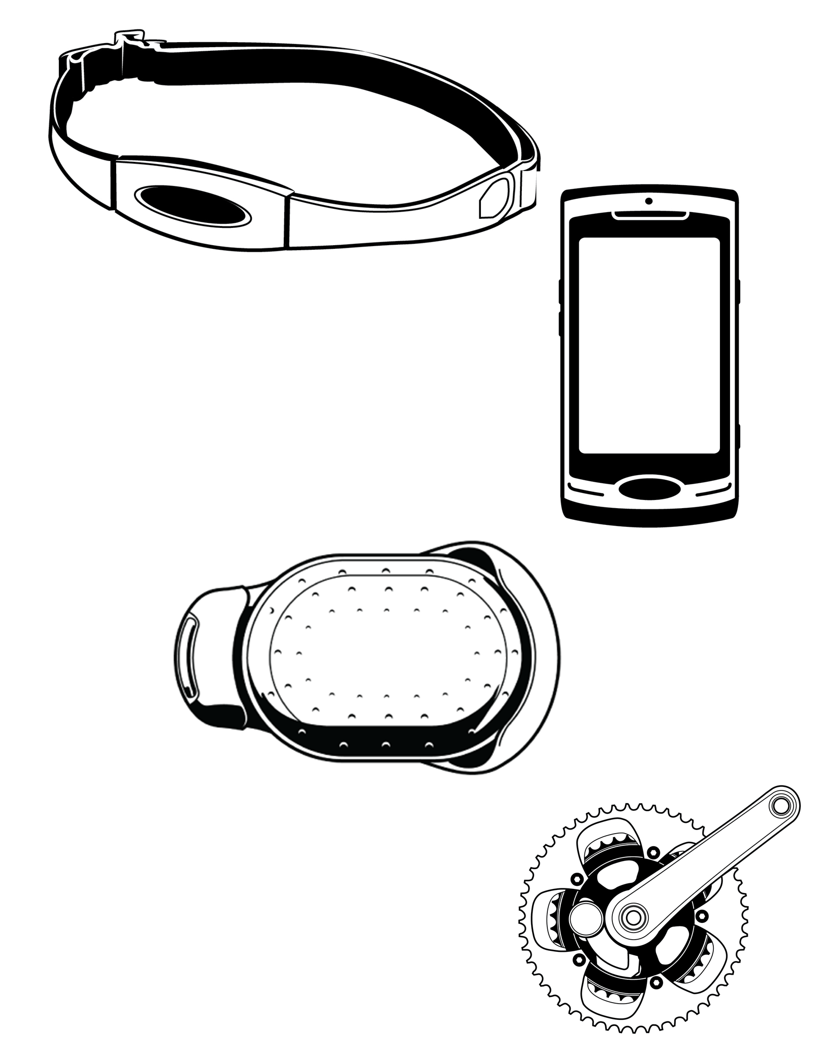
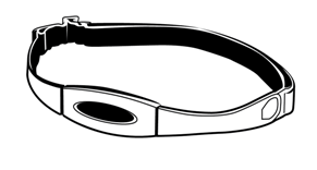
ANT+ heart rate monitors are primarily used to measure the user’s heart rate (beats per minute – bpm) during a given activity in real-time. Heart rate monitors are typically body worn sensors that utilize a variety of technologies to measure the heart rate of the user. The duration of activity for measuring the user’s heart rate varies greatly as does the type of activities a heart rate monitor can be used for.
The ANT+ heart rate monitor is designed to work as a broadcast sensor. This type of sensor reduces network complexity, simplifies the user interaction with the device, and reduces the battery requirements. A broadcast sensor utilizes a one-to-many network topology. This allows multiple display devices to potentially receive heart rate data from the same heart rate monitor. To accomplish this each display device must be configured to receive from the heart rate monitor.
An ANT+ heart rate monitor may also transmit other data in addition to the user’s heart rate that provides more detailed information about the user’s heart rate, as well as data about the heart rate monitor’s make and model. When placed into swim mode, capable ANT+ heart rate monitors transmit swim interval statistics such as average and maximum heart rate during a swim session.


The Fitness Equipment device profile supports two use cases indicated by two seperate icons:

 Personal Use Case
The personal use case of the Fitness Equipment device profile is shown below. The fitness equipment has a relatively small pairing zone, marked by the “Link Here” logo. A user begins a fitness session by approaching the fitness equipment and entering the pairing zone. If the user is wearing a watch, pairing between the watch and equipment will occur when the user places their watch within close proximity to the “Link Here” logo. Once pairing has been established, the range of communication between the watch and FE moves from the pairing zone to the tracking zone. The watch may wirelessly transfer user information and a workout or course file using ANT File Share (ANT-FS) technology and the Flexible and Interoperable Data Transfer (FIT) protocol. The fitness equipment will then begin broadcasting real time workout data which may also include events such as workout starts and stops, as well as lap events. The watch displays and records data, and responds to any events (i.e. starting/stopping chronometer and recording lap events).
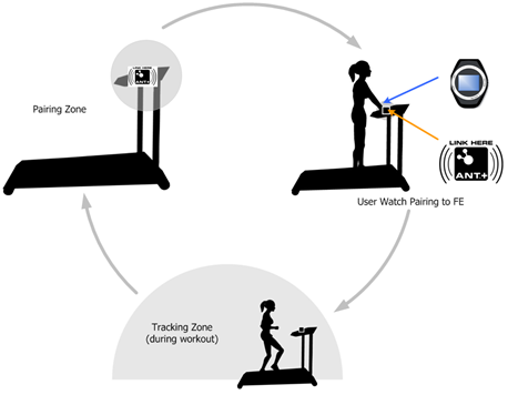
Once the watch and FE have been paired, the watch will provide a file to the fitness equipment containing user information and may also transfer a workout or course profile.
The FE can also broadcast real-time workout data to the paired watch. Different types of FE may send different types of data. For example, treadmills may send speed, distance and incline information, whereas a rowing machine may send strokes per minute and power data. Data may be stored on the watch and summarized at the end of the workout session. The watch may display the summary data at the end of the session, or store it for later download to a PC.
ANT+ Fitness Equipment is designed using a FIT1e module, an application-specific ANT module designed specifically for use in fitness equipment. The FIT1e integrates with fitness equipment to receive ANT+ information from heart rate monitors (HRMs) and exchange information with display devices such as watches.
General data
Equipment specific data
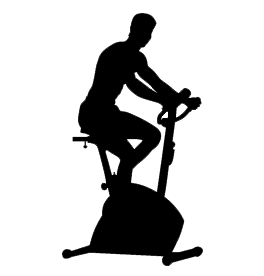
The FE-C use case of the Fitness Equipment device profile allows a smart display (mobile phone, fitness equipment console, bike computer, etc.) to wirelessly control the resistance on an electronic fitness equipment device. Similiar to the personal use case, the fitness equipment device broadcasts real time workout data. The real time data includes general fields like distance, speed and heart rate and also equipment specific data like pedalling power and cadence (bike related fitness equipment). FE-C also allows real time wireless control of the fitness equipment's workout intensity. This allows for interoperable integration of electronic fitness equipment into control displays like mobile workout apps and race simulation systems.
Additional data such as user configuration information, device capabilities, and calibration information can also be exchanged in the FE-C use case to optimize the fitness equipment control.
Relative to the personal use case, the FE-C use case significantly simplifies the pairing process. The simplified ANT pairing process allows multiple displays to connect to the same fitness equipment device, and multiple fitness equipment devices to connect to the same display (group control, fitness classes, etc.).
General data
Equipment specific data

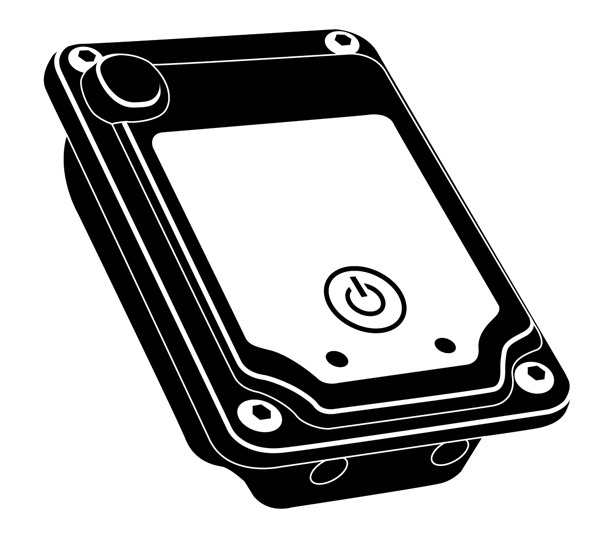
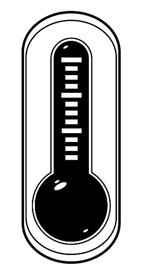
The ANT+ environment sensor is a device that allows a variety of environmental parameters to be measured. Data such as current temperature, and 24 hour highs and/or lows may be transmitted to a collector device for real time display, or stored on the environment sensor for later download to a PC or other collecting device.
Typically the ANT+ environment sensor transmits temperature data at a default 0.5Hz or 4Hz rate.
On receiving a request for data from the display:
The ANT+ environment sensor may store measurement data for transfer to a collection device. The data in the file is formatted according to the Flexible and Interoperable Data Transfer (FIT) protocol and transferred using ANT-FS.
Once an ANT-FS session is established, any stored data available can be downloaded from the environment sensor. The display/collection device may then maintain the ANT-FS session allowing for periodic file transfers of data, or it may disconnect the ANT-FS session, at which point the sensor shall return to the real time data broadcast.

![]()


Bike speed sensors are devices mounted on a bicycle that measure the speed the bicycle is travelling. This is typically done using a magnet mounted on the wheel spokes and a sensor on the bicycle frame that senses the magnet passing. Bike cadence sensors measure the speed at which the user is pedalling, typically using a magnet attached to the pedal shaft and a sensor mounted on the frame. The standard mode of operation is for the bike speed or cadence sensor to transmit its measured data to the receiving display device. Typically this device is a bike computer, but it could be any ANT+ display device capable of decoding bike speed and cadence information, such as a watch, cell phone, PDA, etc.
The ANT+ Bicycle Speed, Cadence, and Combined Bike Speed and Cadence Device Profiles describes the wireless link between the transmitting bike sensors and the receiving display device. The sensors communicate with the receiving device in one of four modes:
 Bike Speed Sensor Only – A single speed sensor on the bike requires a single ANT channel to communicate data.
 Bike Cadence Sensor Only – A single cadence sensor on the bike requires a single ANT channel to communicate data. Bike Speed and Cadence Sensors – Two sensors on the bike (speed and cadence) each require a single ANT channel to communicate data. The receiver must have two active channels, composed of modes 1 and 2, open.
 Combined Bike Speed and Cadence Sensor – This mode has combined both the speed and cadence sensors into a single sensor. One sensor transmits data about the user’s speed and cadence over a single ANT channel.
It is strongly recommended that the receiving display device be able to accept and display data from all four modes of operation. Therefore the use cases and technical content for the different sensors have been put together into this single document. Developers of devices intending to display bike speed and cadence information are requested to implement all the device definitions. The added firmware size to enable all three device profiles in the display device’s firmware is a small cost for the large reward of interoperability with multiple devices.
![]()
![]()
![]()


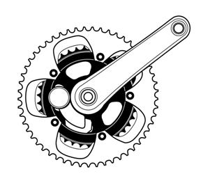
A bike power sensor is a sensor that is mounted on a bicycle and that allows the cyclist to measure his or her power output, which is used to move the bike forward and is measured in Watts. The meter transmits the information to a display device; the device can be a bike computer, watch, cell phone, piece of fitness equipment, or other personal display device.
Bike power sensors vary in two ways: in the method used to measure power and in the conditions and interval used to update and broadcast power information.
The ANT+ message definition currently supports power sensors that use different measurements to determine power:
All of the broadcast power messages have an Update Event Counter that is used by the receiver to calculate information accurately. There are two methods used by bicycle power sensors for information updates:
ANT+ bike power data pages support various types of bike power sensors. The basic power format is implemented using a simple Power-Only message transmitted at a slow rate along with more detailed main power messages at a higher data rate. Main power messages are specific to the power methods used; there are four currently supported methods.

The first three methods, Power only; Torque at Wheel; Torque at Crank; are associated with the icon PWR.
 The fourth method Crank Torque Frequency is associated with the CTF icon.
The information sent in each of these cases is illustrated below and described in detail within the device profile. Devices using the PWR icon are not guaranteed to be interoperable with devices using the CTF icon, and vice versa. It is possible for a display device to carry both icons.


A multi-sport speed and distance monitor (MSM) is a personal device that allows the user to measure the distance travelled and computes the speed at which they are traveling. Unlike stride based systems, this class of sensor may use satellite positioning, radar, or other technologies to measure the distance travelled, allowing MSMs to be used for a wide range of activities with varied user motion and speed ranges. MSMs report distance travelled with an accompanying time stamp and may be used for activities such as running, cycling, alpine skiing, in-line skating, etc.
The MSM is worn on or close to the body and contains an ANT transmitter that broadcasts speed and distance information to a receiver where it may be displayed or stored. Some MSM devices may also have the ability to send other data, such as GPS position. The receiving device can be a watch, cell phone, or any personal display device.
Note: This device profile should not be used for stride based devices such as footpods and pedometers. If you are uncertain about which device profile to use for a sensor that you manufacture please contact the ANT+ Alliance at [email protected] for more information.

![]()

![]()

The ANT+ Geocache Device Profile uses the term geocaching to mean an activity where the user has a GPS receiver which is used to track down a hidden, electronic geocache device.
Typically the owner of the geocache device programs and hides the device, providing general location information, such as the latitude/longitude coordinates or trailhead information to a geocaching website, database or other service. The user may then obtain this information from the service, enter this information into their GPS, and start searching for the geocache device.
The geocache device continuously transmits its ID at a low data rate, allowing it to be detected by a searching GPS receiver. Once the user enters the vicinity of the geocache device, the searching GPS receiver detects the geocache device transmissions and requests an exchange of the geocache device’s data.
 Typical Use
![]()
Programming
![]()

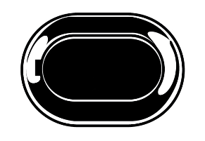
All blood pressure (BP) monitors are designed to take the user’s blood pressure. This is usually accomplished using a sphygmomanometer cuff, which is placed around the user’s upper arm at approximately the same height as the heart. The cuff is inflated until the flow of blood in the brachial artery is momentarily stopped, and then the cuff is deflated until blood flow returns and the arterial pressure is recorded. Electronic BP monitors usually have the ability to display the measured arterial pressure values, as well as other measured and calculated data, such as heart rate and the detection of any pulse irregularities.
An ANT+ blood pressure device will have the ability to store recorded data, and forward this information to another device when required.
Some blood pressure devices may have the ability to store multiple measurements from multiple users. The ANT+ Blood Pressure Device Profile allows for devices to have the necessary scalability to handle multiple users and their associated user profiles.
Note that this device profile does not allow for real time data transfer. Blood pressure data must first be stored in FIT files and then transferred using ANT-FS.
The collection device will store, display and possibly track the data received from the blood pressure device. The collection device can be a device such as a cell phone or laptop computer that may have direct internet access; or it may be a device like a PDA or wrist top computer that will act as a transfer device for the received data.
Ultimately the blood pressure measurements will be stored in a database application, for example an online health database or at a health professional’s office. The information may be transmitted from the blood pressure device to a collection device and then over the internet to a database for storage and possibly further analysis.

Download files:
Upload files (e.g. user profile - optional):
Erase files
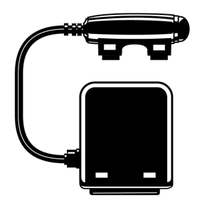
Personal audio devices, video devices, smart phones and other displays are often used during activities that may also be monitored by many traditional ANT+ devices. For example, people that enjoy running will often wear a music player during their workout. Cyclists often use bike computers, but would prefer to keep their hands on the handlebars while operating them. A skateboarder or dancer may choose to mount a video camera remotely to record them as they perform, while also recording their heart rate. In these situations, it is a logical solution to use a single device both to display information received from body worn Personal Area Network (PAN) sensors, and to act as a remote control for the remote device.
The ANT+ Controls Device Profile includes four control use cases, that can be used separately or combined within a remote control or controllable device. Each use case is associated with its own icon and transmits information / control commands as illustrated below.
Audio control allows a user to control their audio player remotely while they work out. For example, a runner may wish to control their music player from their watch as they run.

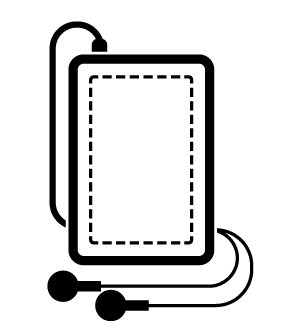
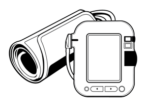
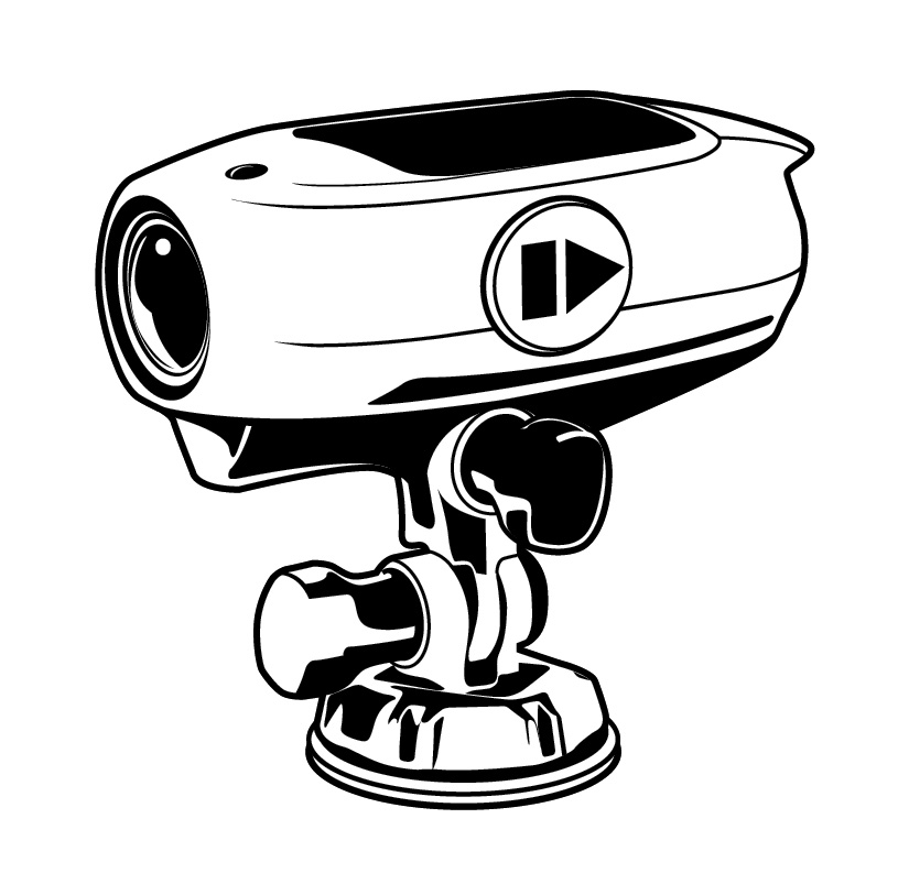
Video control allows a user to control video recording and playback remotely. This could be useful in several situations including:
![]()
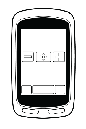
Generic control is used to send generic commands using ANT+. These commands are generic in nature and therefore may be applicable to a very wide range of devices. The commands are also context specific and it is assumed that the user can see the device they are controlling.
Generic control currently includes menu navigation and timer control commands, and is ideal for controlling bike computers, and other fitness equipment displays using a conveniently mounted remote control. It could also be used in combination with other control types, for example video control to operate an ANT+ enabled TV.

Keypad control is used to send individual characters or strings from a remote control to a controllable device. This may be used in combination with other control use cases, for example to enter a user name and passwords, or playlist titles, or for any other situation where short strings need to be transferred wirelessly between devices within a short range.
![]()
Once you have found a device profile that suits your use case, take a look at “How do I implement a profile?”.
If you need to check which device profiles an existing product supports, or vice versa, then use the Product Directory.
